Pump or flow-controlled filling
Useful for repeatable liquid delivery where the pump and product characteristics can be matched. Magnetic, peristaltic, gear and other pump types each suit different hygiene, viscosity and chemical requirements.
Match the dosing principle, nozzle behaviour and container handling to your liquid before deciding how many filling heads the line needs.
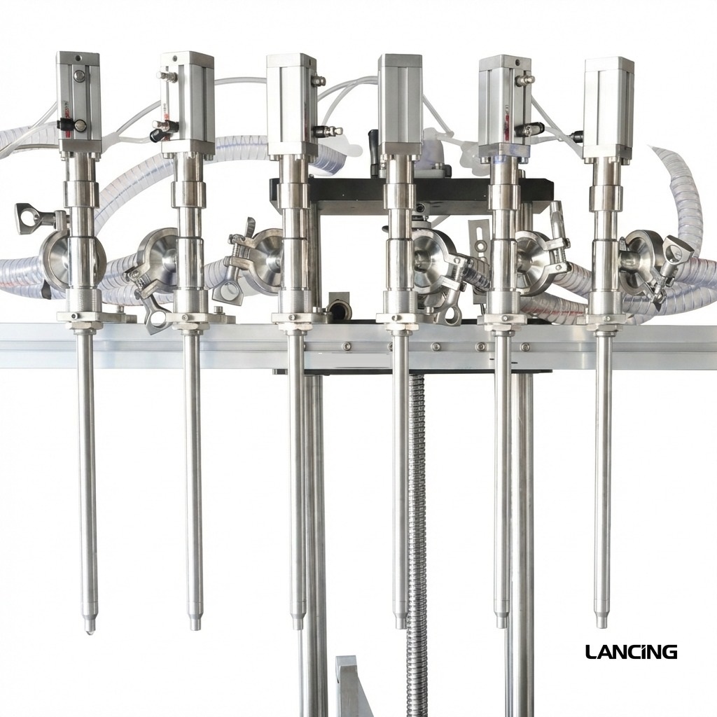
An automatic liquid filler has to do more than dispense a nominal volume. It must control product feed, container presentation, air displacement, foaming, drip cut-off and changeover while maintaining a stable line rhythm.
Water-thin products may favour pump, flowmeter, gravity or vacuum routes. Oils, detergents and shampoos can require positive displacement, diving nozzles or controlled acceleration and deceleration. The right choice is therefore driven by viscosity, surface tension, foam, temperature and chemical compatibility rather than by the product name alone.
The final route should be confirmed against representative product and containers.
Useful for repeatable liquid delivery where the pump and product characteristics can be matched. Magnetic, peristaltic, gear and other pump types each suit different hygiene, viscosity and chemical requirements.
A practical route for oils, viscous liquids and products that need a defined swept volume. Servo control can improve recipe management and motion control.
Suited to rigid containers when a consistent visual fill level matters, particularly for thin and delicate liquids.
The nozzle travels into the container and rises with the product level to control foam, splash and neck contamination.
The details differ by machine, but these stages define the core control problem.
The conveyor, guides and sensors establish a stable pitch before filling.
Gates, screws or tracking control position each container beneath the nozzle set.
The selected pump, piston, flowmeter or vacuum route delivers the programmed fill.
Filled containers transfer to capping, sealing, labelling, coding or accumulation.
A complete enquiry reduces avoidable assumptions and makes machine comparisons more meaningful.
| Product | Viscosity, foam, temperature, solids, abrasiveness and chemical compatibility |
|---|---|
| Fill range | Minimum, maximum and the number of recipes between them |
| Container | Material, dimensions, neck opening, stability and headspace |
| Output | Sustained containers per minute at the real fill volume |
| Accuracy | Target tolerance measured under agreed production conditions |
| Cleaning | Flush, strip-down, CIP expectations and product recovery |
| Integration | Conveyors, capping, sealing, labelling, coding and controls |
Use these configurations to compare machine routes. Final fill range, speed and accuracy are confirmed against your product, container and line.
An indicative configuration for larger liquid fills using six servo-driven magnetic pumps and a 320 litre product tank.
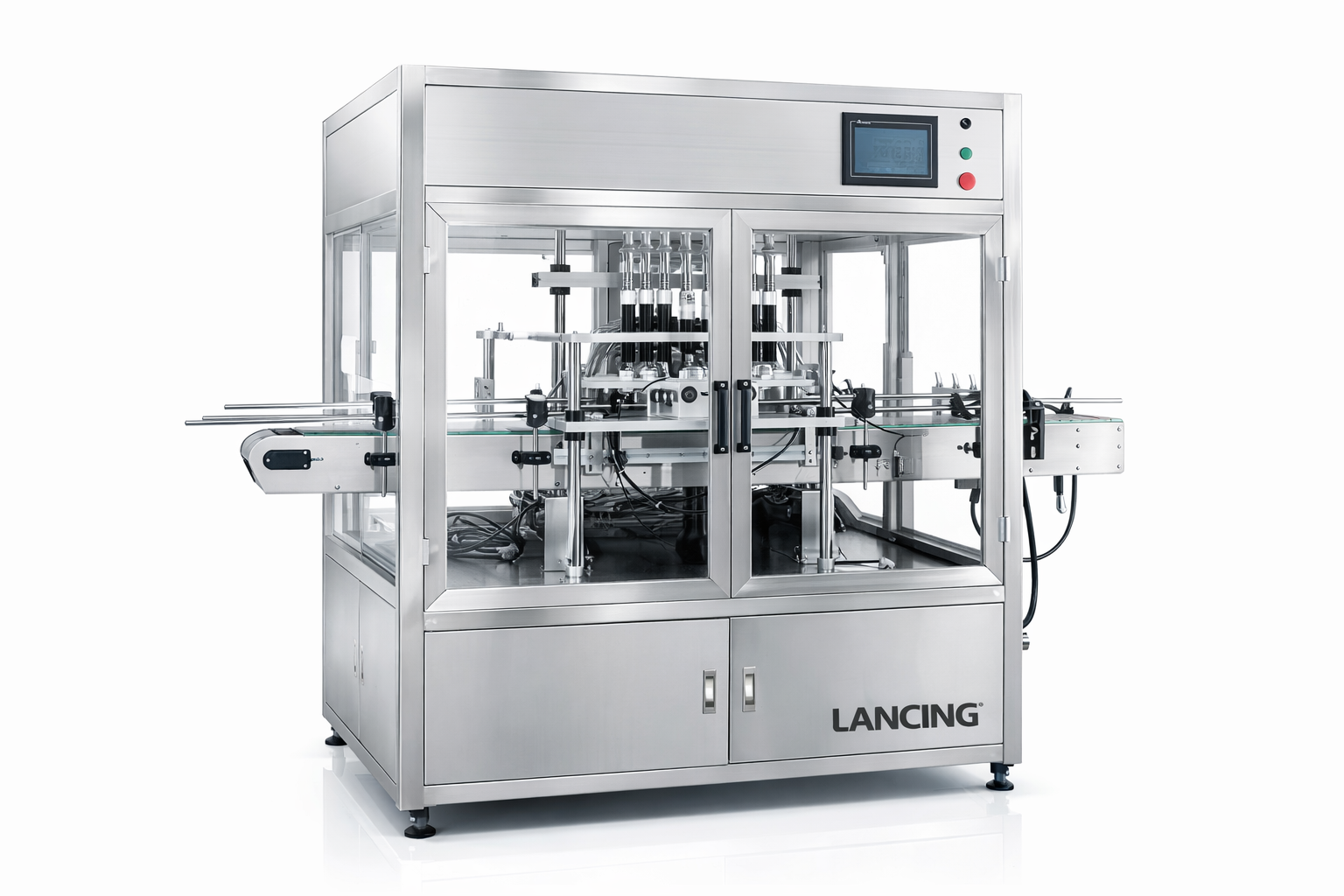
A level-filling route for thin liquids in rigid containers where repeatable presentation is important.
A filler performs best when infeed, closure, labelling and accumulation are sized around the same design rate.
Compare alternative filling methods and the equipment that may be needed before or after the filler.
Answers are general guidance. Final suitability depends on product trials, containers and the confirmed machine specification.
Thin liquids can be filled by pump, gravity, flowmeter or vacuum systems. The best route depends on container rigidity, required accuracy, foam, hygiene and chemical compatibility.
Common controls include diving nozzles, bottom-up filling, staged flow, slower final fill, suitable nozzle geometry and management of the upstream product feed.
Often yes, provided the fill range, container dimensions and neck positions stay within the machine design. Change parts, guide adjustments and stored recipes may be required.
Yes. Conveyor controls, container spacing and line speeds should be designed together so the filler does not create starvation or back pressure downstream.
Compare the next most relevant machine routes before you choose a final specification.
Automatic volumetric filling machines for measured liquid and paste doses, with piston, pump and line-integration guidance for UK manufacturers.
View optionsAutomatic vacuum filling machines for consistent liquid levels in rigid bottles, including perfume, essential oils, juices and other low-viscosity products.
View optionsA production-representative trial should confirm dosing, nozzle cut-off, container presentation and product supply under the conditions the line will actually see.
“Liquid” is not a sufficient specification. The review should capture viscosity at filling temperature, surface tension, foam, entrained air, volatility, solids, lubricity and chemical compatibility. Product can also change as the supply tank empties, as recirculation continues or as temperature drifts. A representative trial should therefore include start-up, steady running, refill and end-of-batch conditions where those stages could alter flow.
Nozzle behaviour deserves separate evidence. A diving or bottom-up profile may help with selected foaming products, while suck-back or a positive shut-off can reduce trailing drips on others. The objective is not simply to avoid a visible drip during one cycle; it is to keep the bottle neck, conveyor and downstream closure area acceptably clean during sustained production.
Product supply must be considered with the filler. Gravity head, transfer pumps, recirculation, balance tanks and pipe dimensions can change pressure at the dosing system. A machine that is repeatable from a stable test vessel may not give the same result if the production feed surges or runs short. The quotation should define where Lancing’s scope starts and ends, what product pressure or level is expected and how low-level, refill and no-product conditions are handled.
This page retains the automatic-selection role. For broader liquid machinery, including compact and semi-automatic routes, use Liquid Fillers UK. Bottle geometry and container-led comparisons are covered more narrowly at Bottle Filling Machines UK.
| Filling route | Where it may fit | Dose/output factors | Accuracy conditions | Cleaning and utilities |
|---|---|---|---|---|
| Peristaltic or tubing-based | Suitable liquids where an isolated, replaceable tube path is an advantage | Tube size, channel count, dose and product behaviour shape cycle time | Tube condition, calibration and stable product presentation must be controlled | Confirm tube change, product recovery, electrical supply and any automatic product feed |
| Pump or flow-controlled | Free-flowing and selected medium-viscosity liquids with a compatible pump or meter | Flow rate, fill profile, nozzle count and container handling determine output | Calibration depends on product condition, supply stability and measurement method | Confirm pump and meter cleaning, pipework, power and product-transfer duty |
| Piston or positive displacement | Liquids needing a defined displacement and controlled shut-off | Cylinder/module choice, stroke, valve size and head count shape the useful range | Valve filling, air exclusion, feed pressure and nozzle cut-off affect repeatability | Confirm strip-down or flush route, seals, compressed air where used and product feed |
| Vacuum level filling | Selected thin liquids in rigid containers where visual level is the control objective | Container seal, neck geometry, recovery and number of stations influence the cycle | Bottle rigidity and neck consistency are part of the test conditions | Confirm vacuum source, returned-product handling and cleaning of tank, nozzles and pipework |
Use the liquid behaviour, bottle set and production feed details to request an automatic-filler shortlist.
Product supply and foaming conditions should be defined before line speed or nozzle count is accepted.
State the product temperature, fill quantity, bottle opening and required output, then test a representative sample. The trial should record foam build-up, nozzle movement, settling time and whether the downstream closure area remains clean.
The dosing system depends on stable product availability. Changing tank level, transfer-pump pressure, entrained air or an inconsistent refill cycle can alter the product presented to the filler, so the supply boundary and expected conditions should be part of the specification.
A repeatable dose depends on more than the filling principle. The supply condition, nozzle movement and container presentation must remain compatible through start-up, steady production, pauses and refill.
Product pressure or level can alter the conditions presented to a pump, piston, flowmeter or valve. At the same time, a nozzle that performs well over a rigid wide-neck bottle may splash, trap foam or contact a lightweight narrow-neck container. The selection review should therefore treat feed, dose, cut-off and bottle transfer as one connected process rather than separate machine features.
| Interface condition | Potential effect | What to test | Acceptance evidence |
|---|---|---|---|
| Changing supply head or pressure | Flow and cut-off can vary as a vessel empties, a pump starts or product is refilled | Start-up, normal level, low level, refill and controlled pause | Recorded fills and clean nozzle behaviour at each agreed condition |
| Entrained air or foam | Apparent volume, surface level and cycle time can change | Production-temperature product using the intended transfer and recirculation route | Agreed fill assessment after the defined settling time, with acceptable neck cleanliness |
| Stringing or trailing liquid | Residue can reach the bottle neck, conveyor or closure station | Nozzle height, shut-off, suck-back where applicable and pause/restart | Sustained run showing the accepted pack condition rather than one isolated cycle |
| Narrow or variable bottle opening | Nozzle access, splash risk and contact clearance become critical | Smallest opening, tallest and shortest bottles, and normal dimensional variation | Stable presentation with no unintended nozzle contact or product outside the pack |
| Lightweight or unstable container | Gating, guide pressure or nozzle motion can tip or deform the pack | Normal gaps, full accumulation, stop and restart at the intended conveyor condition | Containers remain correctly located before, during and after filling |
| Downstream closure sensitivity | Product on the neck can interfere with cap placement, sealing or torque | Fill and closure together using representative bottles and caps | Agreed closure result after a sustained filling sequence |
A useful acceptance run includes transitions as well as steady production.
Confirm the defined start-up route, removal of air, product recovery and the first accepted containers before normal production begins.
Record individual-head results, bottle condition and accepted output while the intended product feed and downstream equipment are operating.
Observe the product supply before, during and after refill so a changing balance-tank level or transfer-pump event does not go untested.
Challenge a planned pause and a downstream block, then verify that held product, nozzle cut-off and container tracking recover in a controlled sequence.
Agree the minimum usable product level, recovery method and behaviour when the supply falls below the normal operating condition.
Demonstrate draining, flushing or dismantling as applicable, then confirm the checks needed before the next product or format is released.
Send the intended product supply, bottles, fill range, closure process and sustained output target for a connected machine review.
Liquid-filling problems often appear at the nozzle but begin at product supply, air entry, temperature, feed pressure or bottle presentation. Specify and test the whole path as one controlled configuration.
| Liquid-filling question | Evidence to collect | Related guidance |
|---|---|---|
| Could tube-based dosing simplify product-path changes? | Liquid compatibility, dose range, suction lift, priming, air, tube specification and campaign length. | Peristaltic filling machines |
| Why does the end of dose create foam, string or drips? | Flow profile, nozzle bore/tip, valve closure, suck-back, insertion depth, bottle opening and pause/restart behaviour. | Filling nozzle selection |
| Why does one head differ from the others? | Head identity, tubing/hoses, valves, seals, restriction, air, calibration and raw individual measurements. | Filling-machine troubleshooting |
| Can the bottle be presented reliably? | Empty/filled stability, opening tolerance, line pitch, sensor state, indexing and recovery after a jam. | Container handling |
| Does the result survive the next station? | Neck cleanliness, foam settlement, bottle deformation, handover time and capping/sealing result. | Automatic bottle filling machines |
A liquid may fill acceptably after the path has stabilised but behave differently at first-off, after a pause or during a tank refill. Include those states in sample trials and acceptance criteria, with the product condition and measuring method recorded.
Include representative product, minimum and maximum dose, production bottles, closure details, output requirement and known foam or drip behaviour. Lancing can identify the right trial route.
The same formulation can fill differently when temperature, aeration, upstream supply or bottle geometry changes. These questions define the conditions a trial must reproduce.
Temperature can change viscosity, density, vapour behaviour, foam, surface tension and the response of seals or tubing. A liquid that runs cleanly from a small room-temperature sample may fill differently after heating, cooling, recirculation or a long hold in production.
State the normal and limiting fill temperatures and condition the sample accordingly. Record temperature alongside dose and appearance results.
Deaeration should be considered when entrained air changes density, dose measurement, foam, visible level or product quality. The source may be mixing, pumping, recirculation or tank refill. A filler cannot always remove air that enters upstream.
Prove the cause before adding equipment. Compare product from normal production with a controlled sample and inspect the feed system for vortexing, leaks or excessive shear.
A smaller opening restricts nozzle diameter, venting and the rate at which product and displaced air can pass without splash or pressure. Container centring tolerance also reduces usable clearance. Increasing pump flow alone can create foam, back pressure or neck contamination.
Supply drawings and production samples, then test the proposed nozzle and fill profile at the required line condition.
A stable feed condition keeps inlet pressure, level, temperature, aeration and composition within the range used for calibration and testing. It includes defined behaviour at low level and during refill, not only a full supply tank.
Record the machine-boundary condition and the alarm or stop response when it cannot be maintained.
Test them together when foam settlement, drips, volatile loss, product skinning, neck contamination or container stability can change before capping or sealing. The transfer delay can be as important as the fill cycle.
Include production closures and realistic conveyor travel. The bottom-up filling guide explains how nozzle motion can affect the final neck condition.
Send the product, pack and production evidence that applies to your line. Lancing can identify the next trial, specification or integration step without treating an assumption as a confirmed result.
After selecting a plausible dosing principle, test the application condition that can change feed stability, nozzle behaviour or the finished pack.
Use representative product and packs, record the actual feed condition, and judge sustained acceptable containers through capping or the next line process.
| Project condition | Why the broad liquid category is not enough | Use this guidance |
|---|---|---|
| Product arrives warm or hot | Viscosity, seal duty, product cut-off and pack stability may change across the temperature range. | Hot-fill filling machines |
| The product or site needs a defined hygienic cleaning method | Cleanability depends on the complete product path, drainage, access, cleaning coverage and verification. | Hygienic design and CIP |
| Bottles are small or have narrow openings | Nozzle bore, venting, centring tolerance and cap handover can limit the useful fill window. | Small-bottle filling |
| The product is a sauce or condiment | Texture, particles, temperature and rim cleanliness should be assessed together. | Sauce filling machines |
Use production product and the actual container range for each route. A water trial cannot establish the behaviour of a foaming, viscous, heated or particulate liquid.
Liquid products can also be controlled by measured flow, pump movement, gravity head, net weight or overflow level. Each route creates a different product path and checking method.
A liquid-filling method proven in a rigid bottle is not automatically a complete solution for a flexible pouch, open paint can or weighed pail. Pack support and the clean closure area can become the limiting conditions before the dosing mechanism does. Define the finished-pack requirements alongside the liquid behaviour.
Compare automatic pouch filling for flexible-pack presentation, paint and coatings filling for industrial colour and product-path issues, and filler feedback and rejection when quantity decisions must close the control loop. Send the product, packaging and required checks for a joined-up machinery discussion.
Send the product, pack and output details that matter. We’ll compare the most practical dosing and line options for you.