Compact automatic line
A smaller-footprint system with essential filling, capping and label functions for a defined container range.
Plan the filler, container handling, closure, label, code and accumulation as one balanced control system.

An automatic filling line can begin with an infeed table or bottle unscrambler and continue through rinsing, filling, capping, sealing, labelling, coding, inspection and end-of-line handling. The best layout depends on the product, pack, output and available floor space.
Line integration is mainly a control and accumulation problem. Each machine has a different cycle, fault mode and changeover requirement. Conveyors and sensors need to absorb short interruptions without creating unstable bottles, excessive back pressure or repeated stops at the filler.
The final route should be confirmed against representative product and containers.
A smaller-footprint system with essential filling, capping and label functions for a defined container range.
Separate machines connected by conveyors allow staged investment and easier future replacement.
Several functions share a compact frame and a coordinated container-transfer system.
Multi-head filling, higher-speed closure and controlled accumulation support larger sustained volumes.
The details differ by machine, but these stages define the core control problem.
Define every transfer from empty container to accepted finished pack.
Use sustained output, not only the fastest individual machine speed.
Provide controlled buffers before and after the critical stations.
Agree emergency stops, speed references, fault handshakes and restart logic.
A complete enquiry reduces avoidable assumptions and makes machine comparisons more meaningful.
| Line scope | Infeed, rinse, fill, close, seal, label, code, inspect and pack |
|---|---|
| Design rate | Sustained containers per minute for each agreed format |
| Efficiency | Planned OEE assumptions, micro-stops and changeover allowance |
| Floor space | Machine footprints, access, guarding and service routes |
| Utilities | Power, compressed air, extraction, water and network |
| Controls | Master line control, emergency-stop zones and data exchange |
Use these configurations to compare machine routes. Final fill range, speed and accuracy are confirmed against your product, container and line.
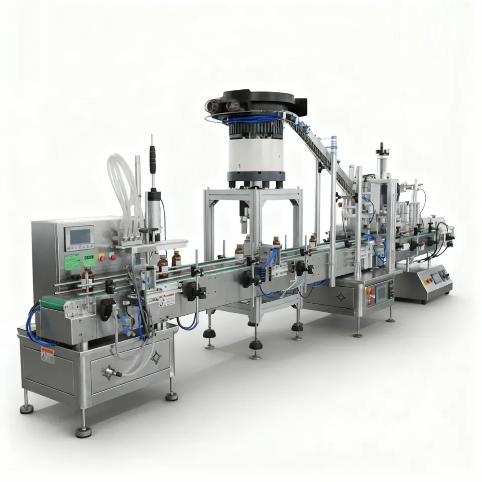
A space-conscious route for filling and downstream bottle finishing within a defined product and pack family.
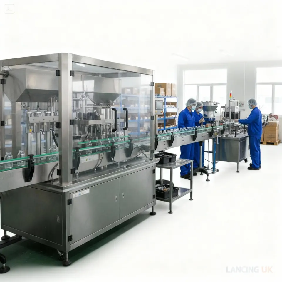
A larger modular production route for higher output, more stations and future capacity planning.
A filler performs best when infeed, closure, labelling and accumulation are sized around the same design rate.
Compare alternative filling methods and the equipment that may be needed before or after the filler.
Answers are general guidance. Final suitability depends on product trials, containers and the confirmed machine specification.
A line may include container infeed, rinsing, filling, capping, sealing, labelling, coding, inspection, accumulation and end-of-line packing. The actual scope follows the pack journey.
No. Each station should have enough margin for its real cycle and expected stops. The line design rate, accumulation and recovery strategy matter more than identical catalogue speeds.
Often yes, provided mechanical transfers, controls, guarding, speeds and documentation can be made compatible. A site survey and interface review are normally required.
Space depends on machine footprints, container travel, access, guarding, operator positions, material flow and maintenance clearance. A scaled layout should be agreed before order.
Compare the next most relevant machine routes before you choose a final specification.
Functional layouts and interface schedules make the filling, capping, labelling and inspection scope clear before a physical arrangement is approved.
A bottle line should first be described as a sequence of functions and control points. The physical drawing can then place those functions within the available floor space while preserving operator access, guarding, cleaning and maintenance routes. The following examples are not model promises; they are useful starting structures for discussing scope.
Bottle loading or infeed, automatic filling, closure presentation or manual placement where appropriate, capping, labelling and discharge. This route can suit projects that need coordinated automatic filling but still allow selected operator tasks.
Unscrambling or accumulation, optional rinsing, filling, cap or pump placement, controlled capping, labelling, coding, inspection and discharge accumulation. The filler and closure stations are balanced around sustained output.
Container preparation, automatic filling with dose or level checks, closure presence and torque or sealing verification, label and code inspection, reject management and end-of-line transfer. This route is considered where traceability and pack verification are central.
Each boundary should identify the physical transfer, normal running signal, blocked and starved conditions, safe stop, fault ownership and restart method. A bottle line can appear to run during a short demonstration yet lose output when one station repeatedly stops another without enough accumulation or a clear recovery sequence.
Container and closure samples should cover the range of tolerances expected in production. Bottle height, base stability, neck position and cap variation influence guides, sensors, chucks, belts and torque. Labels and codes should also be tested on the final pack because line vibration, product residue and curved surfaces can affect downstream quality.
For bottle-led machine comparisons beyond the automatic-line scope, use Bottle Filling Machines UK. For wider filling, capping, labelling and end-of-line projects, use Packaging Lines UK. This page remains the automatic bottle-filling-line selector.
| Interface | Normal production requirement | Blocked or fault condition | Evidence at FAT/SAT |
|---|---|---|---|
| Infeed to filler | Stable bottle pitch and confirmed bottle-present detection | Stop or control infeed without tipping, compression or lost tracking | Run normal gaps, full accumulation and empty-infeed recovery |
| Filler to closure station | Containers leave clean, upright and at a rate the closure process can accept | Prevent uncapped or incorrectly filled packs progressing without the agreed control | Challenge filler stop, closure starvation and rejected-container route |
| Closure to labeller/coder | Closure is present and secure before presentation to labels and coding | Identify missing or unacceptable closures according to the inspection scope | Use representative closures and verify stop/reject signals |
| Labeller/coder to inspection | Pack position supports the required label and code checks | Define what is rejected, where it is rejected and how the event is recorded | Run approved and deliberately challenged packs within the safe test plan |
| Line control and safety | Stations exchange run, ready, blocked, fault and safe-state signals | All equipment reaches a safe condition and restarts in a controlled sequence | Test guards, emergency stops, downstream block and power/air recovery |
| Discharge and accumulation | Finished packs are removed without backing pressure or damage | Control the line when discharge is unavailable | Run full accumulation, controlled stop and restart at the agreed output |
Send the complete bottle, closure, label and room-layout set so the line can be scoped as one production system.
Accumulation, sample variation and station interfaces should be agreed before a layout is approved.
There is no universal amount. Accumulation should be justified from station cycle times, normal short stops, container stability and the cost of stopping upstream equipment. The chosen buffer and control logic should be tested.
Provide representative production samples, including the smallest, largest and least stable bottles plus normal variation in closures. Labels, coding materials and any induction or liner components should be included when they affect the complete pack.
An automatic bottle filling line must control what happens when stations are ready, starved, blocked or recovering. The useful production rate is the accepted output of the complete sequence, not the fastest isolated machine.
Start by defining the normal run condition at every interface: how bottles are presented, what permits the next station to run, where accumulation is allowed and which station controls the stop. Then define the non-normal states that occur in real production. A filler may be ready while the capper is starved of closures, a labeller may be blocked by discharge accumulation, or a bottle gap may interrupt a grouped filling cycle. Each state needs a deliberate response and a defined route back to automatic operation.
Buffer capacity should be expressed as a function, not simply a conveyor length. State which short interruption it is intended to absorb, whether containers may remain uncapped or filled during that period, and what happens when the buffer becomes full or empty. The layout can then be checked against container stability, access, cleaning and the acceptable time between filling and closure.
| Line state | Expected automatic response | Evidence to record | Recovery decision |
|---|---|---|---|
| Normal production | Stations exchange ready and run states while packs remain correctly tracked | Accepted packs, individual station rate, rejects and accumulation level | Confirm the agreed sustained production scenario |
| Filler starved of bottles | No-container/no-fill logic holds the dose and controls upstream demand | Natural gaps and empty-infeed challenge without false fills | Restart automatically only when the required bottle group is present |
| Downstream blocked | Filling stops before uncontrolled backing pressure or trapped containers occur | Full accumulation, controlled stop position and held-pack status | Release in sequence without losing the identity of filled or rejected packs |
| Closure supply unavailable | Uncapped containers are prevented from progressing beyond the agreed control point | Cap-low or cap-empty challenge and affected bottle handling | Define whether packs are held, rejected or manually recovered |
| Interrupted or rejected fill | The affected container and any linked group are identified | Alarm, reject record and physical route for the challenged pack | Prevent an uncertain container re-entering production without an approved check |
| Planned pause and restart | Product, nozzles, conveyors and closures remain in a known condition | First packs after restart, neck cleanliness, closure and label result | Use a defined start-up sequence and first-off release |
| Format changeover | Previous packs, parts, labels, codes and recipes are cleared before release | Line-clearance record and representative first-off packs | Enable automatic mode only after all station checks are complete |
| Utility or power recovery | Equipment returns to a safe state without unexpected movement or dosing | Permitted recovery challenge, homing and retained container status | Require controlled acknowledgement and sequence restart |
Record the normal cycle, short-stop behaviour and recovery loss for filling, capping, labelling, coding and inspection. The station with the lowest sustained accepted output sets the immediate limit, but frequent minor stops can move the practical bottleneck elsewhere. Use the filling line integration guide to define signals, safe states and FAT/SAT challenges across each boundary.
For wider packaging-line engineering beyond filling-led bottle projects, the specialist Packaging Lines UK range covers broader end-of-line scope. This page remains focused on automatic bottle filling, closure and label flow.
Send the station scope, containers, closures, labels and production scenario so the whole line can be balanced around accepted output.
A complete bottle line must remain understandable during material replenishment, cleaning, a blocked downstream station, an interrupted fill and a format change — not only during ideal automatic running.
Define how empty bottles are introduced, spaced, stabilised, detected, filled, released and identified after an interruption.
Show product, packs, operators, guard doors, removed parts, utilities, reject routes and the event each buffer is intended to absorb.
Confirm delivery access, machine envelope, product feed, services, drainage, extraction, interface boundaries and SAT materials.
Test normal flow, starvation, blockage, missing packs, interrupted fills, pause/restart, changeover and connected-station permissions.
| Line event | Filler decision | Downstream/pack decision |
|---|---|---|
| No bottle at one position | Inhibit the affected fill or stop the group according to the agreed architecture. | Retain sequence and avoid a false completed-pack state. |
| Downstream blockage | Stop before accumulation or pack pressure becomes unacceptable. | Protect filled packs, preserve state and define the restart release. |
| Closure unavailable | Decide whether filling stops, a buffer is used or uncapped packs are rejected/quarantined. | Prevent uncontrolled product exposure and mixed pack status. |
| Emergency or power interruption | Move valves, nozzles, drives and conveyors to the designed safe state. | Identify partial or uncertain packs before restart. |
Send the product, bottle and closure family, required sequence, building dimensions and connected machines. Lancing can identify the line-layout and recovery decisions that need to be closed before detailed engineering.
A productive bottle line is defined by how every station behaves during normal running and foreseeable interruptions, not only by the individual machine rates.
The line should stop or slow the equipment that would otherwise continue creating containers the blocked section cannot accept. The exact sequence depends on available accumulation, product in flight and whether stopping the filler would leave uncertain doses.
Define the response for each blockage location and test it with containers present. A generic “line stop” signal is not enough.
Restart should confirm that the downstream path is ready, identify containers held in uncertain states, and release upstream equipment in a controlled order. Part-filled, uncapped or uninspected containers may need rejection before normal flow resumes.
Record the restart sequence and operator prompts in the line control narrative, then verify them during FAT and SAT.
The narrative should describe machine states, permissives, ready/busy/fault signals, accumulation rules, stop and restart sequences, container tracking, rejection, manual modes and response to loss of utilities or product. It should identify which controller owns each decision.
Use it alongside the line-integration guide and interface schedule.
Describe the number and type of containers the buffer can safely hold, the upstream and downstream rates, and the event it is intended to absorb. A time value is meaningful only when those rates and the usable fill range of the buffer are defined.
Include minimum and maximum container formats, pressure limits and the required response when the buffer becomes full or empty.
The choice depends on fill time, pack stability, changeovers, footprint, access and transfer conditions. Rotary is not automatically faster, and inline is not automatically simpler once tracking, grouping or many heads are required.
Compare the two architectures using the inline versus rotary guide and a common production requirement.
Send the product, pack and production evidence that applies to your line. Lancing can identify the next trial, specification or integration step without treating an assumption as a confirmed result.
A monoblock filling and capping machine can reduce transfer distance and footprint when the bottle, product and closure range suit one integrated pitch. Separate machines may remain better where buffering, independent access, future expansion or frequent mixed-format changeovers are more important.
Placing a checkweigher after a filler adds a measurement station; it does not automatically provide useful dose correction or a proven reject function. Confirm which packaging is present at weighing, whether packs can be associated with filling heads, and how a suspect bottle is tracked through any accumulation.
The checkweighing and reject-control guide separates those decisions and provides acceptance challenges. Where the project also includes a flexible refill pack, compare pouch filling rather than assuming the bottle conveyor and capper can serve both formats.
Count correctly filled, closed and accepted packs when comparing complete-line output. Discuss the product-release checks required on your line.
Send the product, pack and output details that matter. We’ll compare the most practical dosing and line options for you.