1. Product flow
Storage/process vessel, transfer, filler feed, recirculation, recovery, cleaning connections and waste route.
A useful layout shows how product, containers, people, utilities, faults and change parts move through the area — not only where each machine frame fits.
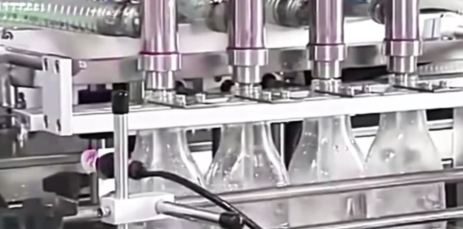
Each layer exposes a different constraint. Review them together before equipment positions, conveyor lengths and utility drops are fixed.
Storage/process vessel, transfer, filler feed, recirculation, recovery, cleaning connections and waste route.
Infeed, orientation, spacing, filling, closure, labelling, coding, inspection, rejection, accumulation and packing.
Operator stations, replenishment, sample points, change parts, pallets, closures, labels and finished packs.
Guard doors, maintenance removal space, lifting, isolation points and safe routes during production and cleaning.
Electrical, air, network, extraction, drainage and interface routes without creating trip, hygiene or maintenance conflicts.
Where packs stop, accumulate, reject or are reconciled after a jam, partial fill, blockage or power interruption.
These are planning patterns rather than fixed designs. The product, pack, building and integration requirements determine the final arrangement.
| Layout pattern | Useful when | Questions to resolve |
|---|---|---|
| Straight modular line | Process sequence and building length allow clear upstream-to-downstream flow and separate station access. | Total length, buffer locations, return routes, operator crossings and future station insertion. |
| Compact return/U-shaped line | A smaller operating zone or shared operator access is valuable and pack turnarounds are stable. | Corner transfer, pack orientation, congestion, guarding, replenishment and separation of empty/finished packs. |
| Combined/monoblock cell | Close control between filling and closure is required, and the pack family suits dedicated handling. | Format flexibility, access within the cell, single-point stoppage, cleaning boundary and downstream handover. |
A buffer can absorb a short downstream interruption, protect a continuous process or give an operator time to replenish materials. It cannot permanently correct a slower station. State the event, required duration, allowable pack pressure and recovery sequence before choosing conveyor length or accumulation method.
Add the swept area of guard doors, control-panel doors, hoppers, product-path parts, pumps, nozzles and format tooling during cleaning or maintenance. This often reveals access conflicts that the closed-machine footprint hides.
Walk the layout as an operator, cleaner, maintenance technician, material handler and visitor. Then repeat the walk for a blocked line and a format change.
Send a dimensioned site sketch, production sequence, machine interfaces, product-feed point and container flow direction. Lancing can identify layout assumptions that should be closed before a detailed line proposal.
Allow the machine and guarding envelope plus operator positions, doors, change parts, cleaning, maintenance, product replenishment, utilities, material routes and safe access. Exact clearances depend on the selected equipment and site assessment.
Place controlled buffer where it protects the required station interaction without allowing unstable pack pressure or hiding a persistent bottleneck. The layout should define what event the buffer is intended to absorb.
One station or line controller needs clear speed ownership, but the decision depends on the process. The control strategy must define permissions, blocked/starved states and how each station follows or stops.
Reserve credible space, utilities, control interfaces and conveyor handovers for named future functions. Undefined spare space is less useful than an agreed expansion scenario.
A line can fit geometrically yet be difficult or unsafe to clean, change or maintain. Routes reveal clashes between normal production, material supply, open guard doors and removed components.
Send the product, pack and output details that matter. We’ll compare the most practical dosing and line options for you.