Mechanical transfer
Conveyor height, guide rails, gaps, side transfers, container support and access determine whether packs move reliably.
Treat every transfer, sensor, buffer and fault state as part of the filling project so the complete line reaches its sustained output safely.

The process map establishes the scope, interfaces and ownership of every operation.
Unscramble, load or accumulate empty containers.
Rinse, clean, inspect or orient the container.
Locate, dose and release with no-container/no-fill control.
Feed, place and secure caps, lids, plugs, pumps or crimps.
Seal, label, code, inspect and reject non-conforming packs.
Accumulate, case pack or transfer to the next process.
A mechanically connected line is not integrated until controls, safety and production recovery are also defined.
Conveyor height, guide rails, gaps, side transfers, container support and access determine whether packs move reliably.
Ready, run, blocked, starved, fault and emergency-stop states require a documented interface.
Guarding, interlocks, emergency stops and restart logic must cover the combined line and its operating modes.
Machine margins and accumulation allow the line to recover from short interruptions without repeated full stops.
A practical line model includes cycle time, efficiency, changeover and buffer recovery.
| Design rate | Agreed sustained containers per minute for each format |
|---|---|
| Machine margin | Rated capacity above design rate where technically sensible |
| Accumulation | Buffer time or container count at critical interfaces |
| Changeover | Planned time and sequence for product and pack changes |
| Efficiency | Assumed uptime and micro-stop allowance |
| Rejects | Detection, tracking and safe removal without line confusion |
A line should stop predictably, retain container tracking where required and restart without double filling or losing the closure sequence.
A machine can pass factory testing and still fail to reach production if site interfaces are not ready.
Answers are general guidance. Final suitability depends on product trials, containers and the confirmed machine specification.
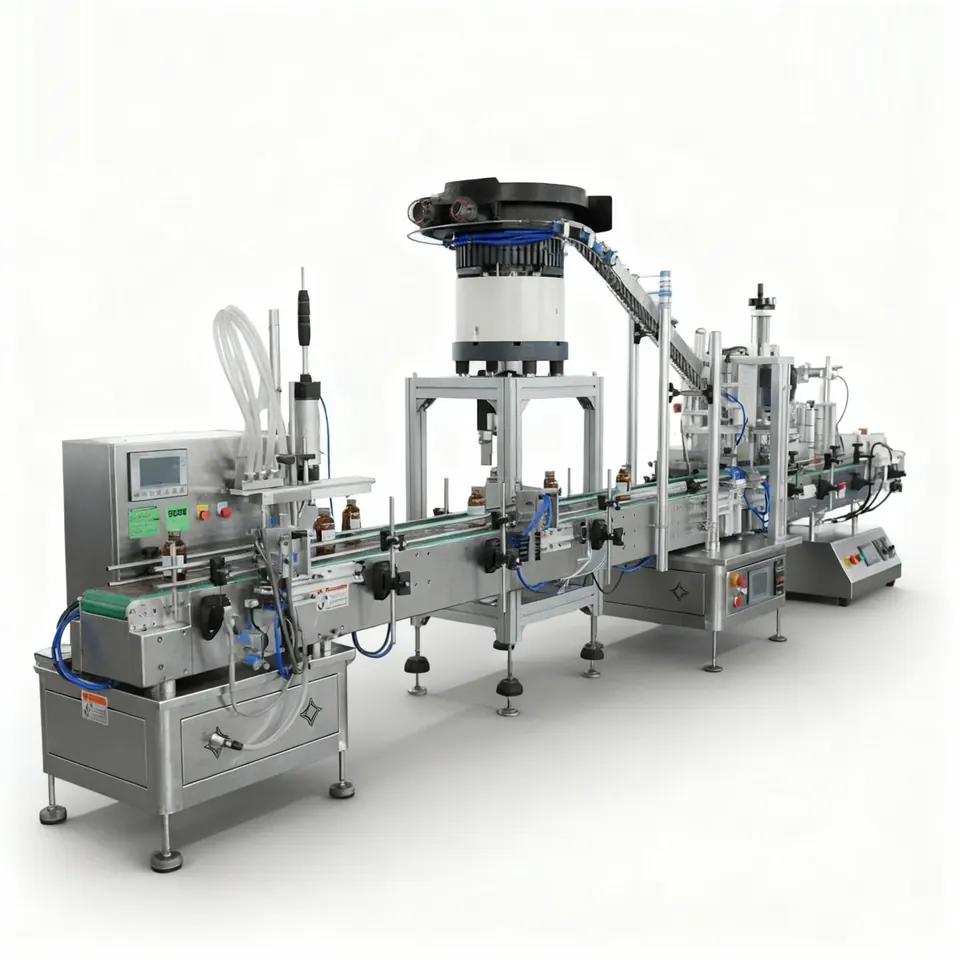
It is the mechanical, electrical and control work that connects container infeed, filling, closing, labelling, coding, inspection, conveyors and accumulation into one production system.
The answer depends on the process. A master line controller or nominated primary machine should set a coordinated speed reference while each station manages local sensors and faults.
Accumulation absorbs short differences in machine cycles and micro-stops so one brief interruption does not stop the entire line.
Often yes after a survey of conveyor heights, speeds, controls, emergency stops, guarding, pack transfers, documentation and available space.
Compare the next most relevant machine routes before you choose a final specification.
Automatic bottle filling lines integrating filling, capping, labelling, coding, inspection and conveyors for UK liquid, paste and chemical production.
View optionsUnderstand automatic filling machine accuracy, repeatability, throughput, head count, line efficiency and performance testing before quotation.
View optionsRequest an automatic filling machine quotation from Lancing Ltd. Send product, container, fill range, output and line-integration details.
View optionsAcceptance criteria should show how the filler, conveyors, closing, labelling and safety systems behave together in normal and abnormal production states.
FAT and SAT are most useful when they test the agreed line behaviour rather than repeat a general demonstration. The control narrative should define normal running, starved and blocked conditions, planned stops, guarded access, faults and recovery. Each acceptance test can then identify the starting condition, action, expected response and evidence to record.
Factory acceptance should focus on functions that can be represented safely before delivery: product and pack handling, dosing, line handshakes, alarms, recipes, changeover, guarding and documentation. Site acceptance should confirm installation-specific conditions such as final utilities, product feed, room layout, interfaces to retained equipment and sustained performance in the production environment.
The test product and packs must be agreed. A substitute may be useful for early mechanical checks but cannot prove behaviour that depends on viscosity, foam, particles, dust, chemical compatibility or pack variation. Where full production material cannot be provided, the acceptance record should distinguish what was demonstrated from what remains to be confirmed on site.
For broader capping, labelling, conveying and end-of-line line ownership, use Packaging Lines UK. This page remains focused on integrating the automatic filler and its controls with the connected production system.
| Function | Factory acceptance evidence | Site acceptance evidence | Record to retain |
|---|---|---|---|
| Product dosing | Representative dose checks by head and format using agreed product or documented substitute | Production product checks under final feed, utilities and environmental conditions | Samples, reference method, results, adjustments and approved settings |
| Sustained output | Timed run using agreed pack and line scope, with rejects and stops recorded | Timed production run with final upstream/downstream equipment and operators | Start/finish time, accepted packs, rejects, stops and calculated sustained output |
| Container and closure handling | Normal variation, gaps, starvation, blockage and change-parts demonstration | Final material supply, room layout, operator replenishment and retained-equipment interfaces | Approved samples, challenge results and outstanding limitations |
| Controls and line states | Run, ready, starved, blocked, fault, guard-open, emergency-stop and restart challenges | Signals to site equipment, remote services and production reporting where included | Cause-and-effect results, alarm list, backups and software/recipe references |
| Cleaning and changeover | Agreed strip, flush, recovery or dry-clean tasks plus one representative format change | Site cleaning agents, waste route, hygiene controls and operator execution | Task steps, parts, time, verification checks and any unresolved risk |
| Documentation and handover | Manuals, drawings, parts lists, declarations or certificates included in scope | Installed revisions, training attendance and site acceptance closure | Controlled document index, training record, snag list and signatures |
The filler has insufficient containers or product. The response should protect product quality, avoid empty fills and allow a controlled return to production.
Downstream equipment cannot accept more packs. The control strategy should stop or buffer the correct stations without losing container tracking.
Motion and product flow must reach the defined safe condition. Recovery should require the intended checks and should not release an uncertain pack.
Use the line narrative and acceptance matrix to make supplier scope, FAT and SAT directly comparable.
FAT, SAT and open items need clear ownership and evidence across the connected line.
FAT demonstrates agreed functions at the supplier or build location using the available product, packs and interfaces. SAT confirms site-dependent installation, utilities, retained-equipment interfaces and production performance after delivery.
Record the unmet criterion, reason, responsible party, required evidence and the stage at which it will be closed. Site-dependent items should not be treated as passed merely because they could not be represented at FAT.
An interface is not complete because both machines have a conveyor or a spare signal. Name the physical handover, expected state, fault response, connection point, test method and responsible party.
| Interface | Define before design release | Acceptance evidence |
|---|---|---|
| Product supply to filler | Tank/pump ownership, pressure/level/temperature, connection, isolation, recirculation, refill and cleaning boundary. | Start, steady run, refill, starvation and cleaning/recovery checks. |
| Container infeed | Pack orientation, pitch, stability, height, speed ownership, blocked/starved states and maximum pressure. | Repeated normal infeed plus missing, double, fallen and blocked pack responses. |
| Filler to closure station | Pack state, spacing, neck cleanliness, settlement time, buffer and interrupted-fill handling. | Filled packs transferred through normal, blocked and restart conditions. |
| Coding/inspection/reject | Trigger source, data, good/reject definition, reject confirmation and reconciliation. | Known-good, known-fault and missing-confirmation tests. |
| Line control | Master speed, permissives, faults, reset ownership, emergency interfaces and restart sequence. | State matrix demonstrated across connected stations. |
| Utilities/data/site | Connection point, quality/capacity, network approval, isolation and installation ownership. | Site-readiness record and SAT checks. |
Use the line-layout guide to place interfaces physically, the site-preparation guide to verify services, and the FAT/SAT guide to turn each interface state into an observable test.
Provide the proposed station sequence, supplier boundaries, product-feed arrangement and control requirements. Lancing can help structure the interface schedule for a complete filling project.
Mechanical fit is only one part of integration. The project also needs a shared definition of signals, control ownership, manual modes, resets and container status.
An interface responsibility matrix lists every mechanical, electrical, control, product, utility and documentation boundary and names who designs, supplies, installs, tests and approves it. It prevents gaps between machine suppliers, site contractors and the customer.
Use the matrix from design review through SAT and close each open item with evidence rather than verbal agreement.
Each signal should have an unambiguous condition, owner, fail state and reset rule. “Ready” might require guards closed, no fault, correct recipe, utilities available, product present and downstream capacity. Different controllers must not assume different meanings.
Document signal direction, voltage or protocol, timing and the effect of loss or stale communication.
Manual and maintenance modes are used for setup, clearing, cleaning and fault recovery, where people may be closer to hazards and inter-machine assumptions can change. A line that runs in automatic mode can still have unsafe or confusing manual interactions.
Test authorised controls, speed or hold-to-run limits, interlocks, container movement and the effect on connected machines.
Resetting an emergency stop should not by itself restart hazardous movement or release uncertain containers. The line should confirm safe conditions, require a deliberate restart action and manage products or packs affected by the stop.
The site-specific risk assessment and control narrative must define the reset and recovery sequence for the complete integrated system.
The line needs a reliable method to associate a fault or inspection result with the correct physical container until it is removed or otherwise controlled. Simple time delays can become unreliable when accumulation, gaps or stops change the order.
Define tracking boundaries, sensor confirmation, reject verification and the response when the reject device or container detection fails.
Send the product, pack and production evidence that applies to your line. Lancing can identify the next trial, specification or integration step without treating an assumption as a confirmed result.
Combining filling and capping on one platform does not remove line-integration work. The monoblock guide explains shared indexing, cap feed, format change and cleaning; this integration page remains the owner for conveyors, accumulation, inspection, coding, line states and recovery outside the compact machine.
A complete line needs a defined accepted-product route, not only machine-ready signals. A fill-complete bit does not prove a closure is correct, a weight result is valid or a rejected pack has been removed. Agree which station makes each decision and what happens to packs whose status becomes uncertain during a stop.
Review quantity checks, filler feedback and confirmed rejection together. Include unavailable inspection, loss of communication and a pending reject in the controls narrative. For flexible-pack lines, identify the point where pouch support ends and finished-pack stability becomes an outfeed responsibility.
An interface schedule should name the decision owner, signal or data, delay, fault response and restart authority for each boundary. Send the existing line sequence and controller details for an integration review.
Send the product, pack and output details that matter. We’ll compare the most practical dosing and line options for you.