Indexed multi-head filling
A group of containers stops beneath a matched nozzle bank for each fill cycle.
Increase productive fill time with two, four, six, eight, ten, twelve or project-specific nozzle counts while keeping the product feed and conveyor balanced.
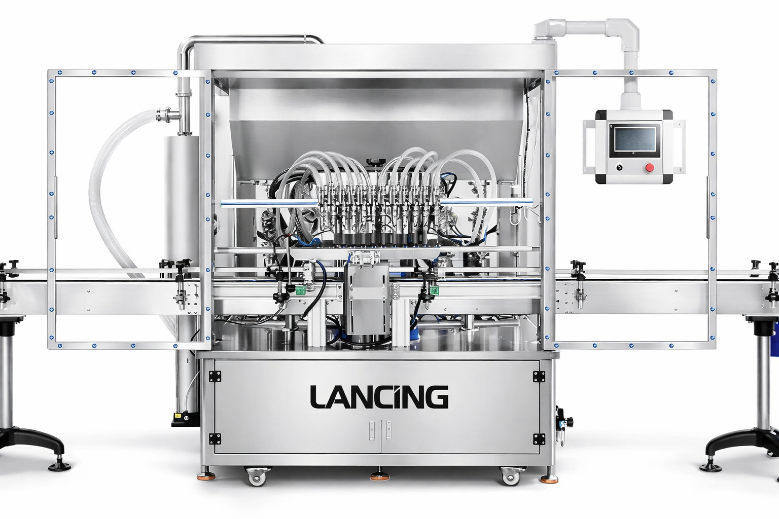
A multi-head filler doses several containers during each index or while containers move. It can raise output, but only if the product supply, container spacing, nozzle timing and downstream equipment are sized for the same sustained rate.
The useful comparison is cycle time at the real dose, not a theoretical machine speed. Long fills, foam control, container settling and capping capacity can all determine whether four larger nozzles perform better than a greater number of smaller ones.
The final route should be confirmed against representative product and containers.
A group of containers stops beneath a matched nozzle bank for each fill cycle.
Nozzles follow moving containers, reducing the stop-start effect on the conveyor.
A common product feed supplies matched dosing elements and needs balanced pressure and cleaning.
Each head can be adjusted or monitored separately where the machine architecture supports it.
The details differ by machine, but these stages define the core control problem.
Use the real dose, viscosity, nozzle bore and foam-control profile.
Indexing and guide design establish how many containers can be filled together.
Pumps, hopper and pipework must replenish all heads without starving them.
Capping, labelling and accumulation are matched to sustained filler output.
A complete enquiry reduces avoidable assumptions and makes machine comparisons more meaningful.
| Head count | Selected from required output and actual cycle time |
|---|---|
| Head balance | Calibration, equal product feed and individual adjustment |
| Manifold | Flow distribution, dead volume, drainage and cleaning |
| Pitch | Container diameter, stability and indexing method |
| Changeover | Nozzle spacing, guide adjustment and recipe control |
| Expansion | Frame, controls and product-feed capacity for future heads |
Use these configurations to compare machine routes. Final fill range, speed and accuracy are confirmed against your product, container and line.
A high-nozzle-count system for automatic paste or viscous-liquid production.
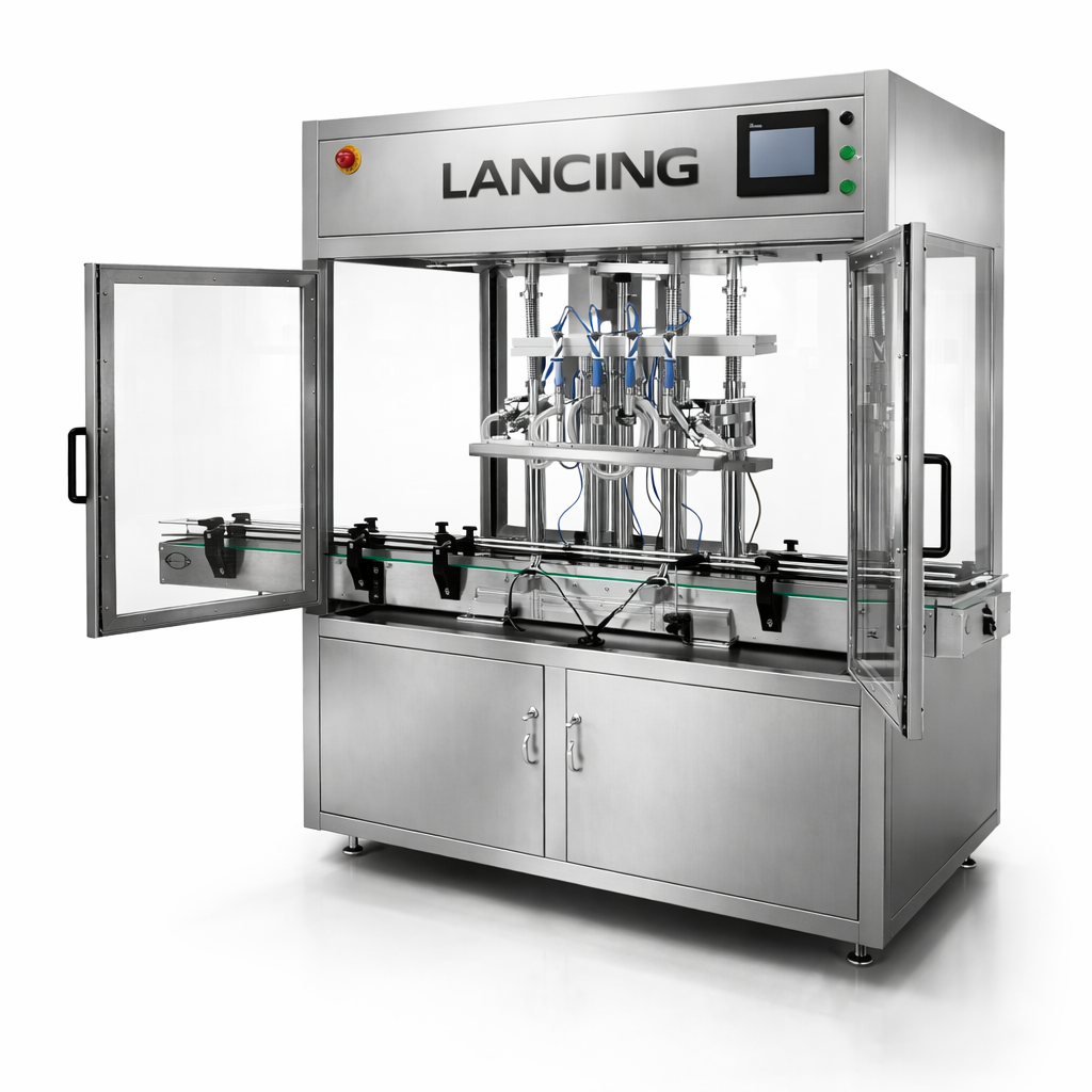
A mid-range nozzle bank that can balance footprint, changeover and production output.
A filler performs best when infeed, closure, labelling and accumulation are sized around the same design rate.
Compare alternative filling methods and the equipment that may be needed before or after the filler.
Answers are general guidance. Final suitability depends on product trials, containers and the confirmed machine specification.
Not always. Output also depends on fill time, indexing, product replenishment, container stability and downstream machines. The line must be modelled as a system.
Many multi-head systems allow head-specific adjustment. The exact method depends on whether the heads share a drive, use separate pumps or have individual servo control.
The design should minimise dead legs and provide a defined drain, flush or strip-down method. Cleaning validation depends on the product and industry.
Often yes within the mechanical adjustment range. Large changes may need a different manifold, nozzle beam or change parts.
Compare the next most relevant machine routes before you choose a final specification.
Automatic servo filling machines with programmable recipes, controlled fill profiles and multi-head options for liquids, creams, sauces and pastes.
View optionsAutomatic tracking-head filling machines that follow moving bottles for continuous conveyor operation with liquid, cream, shampoo, detergent and paste products.
View optionsA multi-head filler only raises useful output when product supply, container groups, downstream machinery and cleaning can support the wider bank.
Head count is a capacity decision, not a quality claim. The useful number of nozzles depends on the time needed to present a complete group of containers, deliver the dose, withdraw or cut off cleanly and release the group without starving the next station. A wider bank can increase theoretical filling capacity while creating new constraints in product distribution, conveyor indexing, guarding, cleaning and changeover.
The product supply system should be sized and controlled as part of the filler. Each head needs the same product condition at the same point in the cycle. Manifold pressure, hopper level, refill events, temperature and entrained air can create head-to-head differences. Acceptance should record individual heads, not only an average across the machine, and should include a representative pause and restart.
Container accumulation must support the group size. The infeed needs enough stable packs to form each index without excessive gaps, while the discharge and downstream equipment must clear the group. If the capper, labeller or inspection station is slower, the line needs a deliberate buffer and stop/restart strategy rather than simply a faster filler.
Multi-head automatic systems may use piston, pump, flow, auger or weighing principles. Use the relevant technology page to confirm product suitability first, then use this page to decide whether parallel heads create useful sustained output.
| Constraint | Question to answer | Evidence required | Design response |
|---|---|---|---|
| Dosing cycle | What is the stable fill time at the real dose and product condition? | Timed representative cycles including nozzle movement and cut-off | Select a practical head count rather than multiplying an unverified headline rate |
| Product distribution | Can every head remain supplied without pressure, level or temperature imbalance? | Individual-head results before and after refill, pause and restart | Size and control hopper, manifold, pumps or transfer system as part of the filler |
| Container indexing | Can the line form and hold each group without gaps, tipping or contact? | Run the least stable container through normal and stop/start conditions | Provide guides, gating, nests, sensors and accumulation matched to group size |
| Downstream capacity | Can closing, labelling, coding and inspection accept the filler discharge? | Compare sustained cycle and recovery behaviour at each station | Balance station rates and add controlled accumulation where justified |
| Changeover and cleaning | Can every nozzle, hose, valve and guide be changed and verified within the production plan? | Observed changeover with parts identified and a documented line-clearance check | Reduce unnecessary variants, improve access and store approved settings |
| Fault handling | Can an affected head or container be identified without releasing an incorrect pack? | Challenge missing container, blocked nozzle, low product and downstream stop | Define alarms, head isolation, reject tracking and restart logic |
Use sustained line evidence—not nozzle count alone—to justify a multi-head automatic filling machine.
Head count should be accepted through individual-head data and complete-line capacity evidence.
Measure each head separately using the same product, dose, container and reference method. Repeat the check after start-up, a planned pause and a normal product refill so feed or air differences are visible.
That depends on the machine design and control strategy. The quotation should state whether a head can be isolated, how container tracking and rejects are handled, and what effect the condition has on line output and acceptance.
Parallel nozzles increase useful output only when the dosing channel, shared product feed, container group and downstream line remain controlled as the head count increases.
Begin with one representative channel and the most demanding product and dose. Prove the product-contact route, nozzle cut-off and measurement method before multiplying the result. The next stage is not simply to run every head once; it is to determine whether common feed conditions create a difference between the first and last channel, between the start and end of a batch, or before and after a pause.
Each head should have a permanent identity in the test record. Samples taken in nozzle order make it possible to separate a common-feed issue from a local valve, hose, calibration or nozzle issue. Where the machine uses independent dosing channels, record the approved correction or calibration status for each head. Where several heads share a manifold or hopper, challenge level and refill conditions that could change distribution.
| Scale-up stage | Evidence to collect | Decision before progressing | Typical issue exposed |
|---|---|---|---|
| One channel | Representative product, minimum and maximum dose, nozzle cut-off and repeat samples | Confirm the dosing principle and product path are suitable | Wrong valve, nozzle, pump, piston or motion profile |
| Complete head bank | Samples identified by head and sequence under stable product supply | Confirm all heads meet the agreed assessment method | Local calibration, hose, valve or distribution difference |
| Container group | Least stable packs through gating, location, filling and discharge | Confirm the group forms and clears without contact or lost tracking | Gaps, tipping, guide pressure or incorrect nozzle alignment |
| Sustained refill cycle | Head-by-head results before, during and after product replenishment | Confirm common feed remains stable across the bank | Level, pressure, temperature or aeration change |
| Pause and restart | First containers after planned pause and downstream blockage | Confirm held product, head status and container records recover correctly | Drip, overfill, missed container or stale tracking state |
| Complete line | Accepted packs, rejects and station states over an agreed production scenario | Confirm extra heads create sustained line output | Capper, labeller, inspection or accumulation becomes the bottleneck |
If every head changes together, investigate shared product supply, temperature, aeration, refill timing and the common recipe. If one head alone changes, investigate its product path, dosing module, valve, nozzle, calibration and mechanical alignment. If the result follows a container position rather than a head, inspect pack presentation, sensor timing and the indexing group.
For systems with programmable individual axes, the automatic servo filling machine page explains recipe and recovery control. Where containers continue moving during dosing, compare the motion and tracking requirements on the tracking-head filling machine page.
Send the real fill cycle, product-feed arrangement, containers and downstream rates so head count is justified by sustained line evidence.
Adding heads increases potential output only when product distribution, container presentation, settings, maintenance and downstream capacity remain controlled across the complete bank.
| Observed pattern | Likely investigation level | Evidence to retain |
|---|---|---|
| All heads move together | Common product feed, pressure/level, temperature, air, recipe, reference method or line event. | Time trend, refill/pause state, common settings and raw head data. |
| One head is biased | Head-specific tube/hose, seal, valve, restriction, nozzle, calibration or mechanical setup. | Permanent head identity and controlled component/substitution checks where authorised. |
| Position follows the bottle, not the head | Container tare, opening, stability, indexing position or sensor timing. | Bottle/position identity and container-handling video. |
| Variation appears after restart | Drain-down, air, product settlement, temperature, path recovery or restart sequence. | Pause duration, machine state and first samples from every head. |
| Bank output is below expectation | Fill time, indexing, product supply, pack spacing, downstream blockage or excessive interventions. | Station cycle times and complete-line state history. |
Use the sample-trial sequence to qualify one channel and then the complete bank, the container-handling guide to verify every fill position, and the troubleshooting guide to separate common from channel-specific causes.
Send the dose, product, bottle pitch, required run window and connected-station capacities. Lancing can assess whether more heads, a different fill principle or improved line balance is the useful route.
Send the product, pack and output details that matter. We’ll compare the most practical dosing and line options for you.